
CAD plans printed 1:1 onto the floor.
Faster and more accurate than a chalk line: we print your layout with HP SitePrint directly onto hall and construction-site floors, with millimetre precision – including axes, arcs and labels.
See how a layout takes shape – watch the live demo ↓- 1:1 from your CAD file
- Millimetre precision
- Checked against your reference points
- Weekend work possible
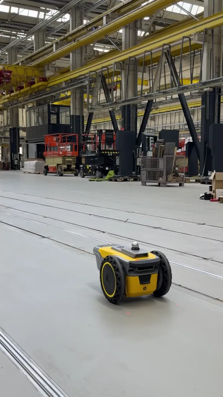
- HP SitePrint
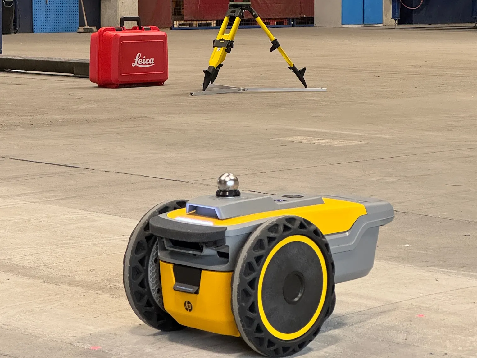
- Leica total stations
- Trained at ALLSAT in Hanover
- Working internationally
The difference
Leave the chalk line and spray can behind.
Marking out with string, a tape measure and a spray can works – until the geometry gets complex. Then every line takes time, and every transfer error carries through.
| Feature | Chalk line & tape measure | Layout printing |
|---|---|---|
| Transfer | Chalk line & tape measureMeasured and marked by hand, point by point | Layout printing Automatically, directly from your CAD file |
| Arcs, circles, angled lines | Chalk line & tape measureTime-consuming – every shape adds to the time required | Layout printing No extra effort – printed as drawn |
| Labels | Chalk line & tape measureAdded by hand with a spray can or pen | Layout printing Text and axis labels printed at the same time |
| Accuracy | Chalk line & tape measureReading and transfer errors add up | Layout printing An internally consistent print, referenced to your fixed points |
| Plan changes | Chalk line & tape measureMeasure again, mark again | Layout printing Update the data, print again |
| Verification | Chalk line & tape measureRecheck with a tape measure | Layout printing Checked on site against agreed reference dimensions |
Applications
Versatile applications.
HP SitePrint transfers digital CAD plans precisely at 1:1 scale directly onto floor surfaces, including complex geometries and labels. This reduces manual measuring and marking effort, minimises transfer errors and simplifies the execution of your plans.
- 01
Industry & manufacturing
Machine layouts for hall planning, production lines and assembly workstations.
- 02
Warehousing & logistics
Positions of rack feet and anchor bolts in high-bay warehouses, storage areas and picking zones.
- 03
Drywall & interior fit-out
Wall set-out, room layouts and door openings – on large construction sites too.
- 04
Structural & concrete work
Positions and contours for components and formwork.
- 05
Building services
Positioning and installation aids for heating, ventilation, plumbing and electrical installations.
- 06
Conveyor systems & intralogistics
System routes, transfer points and planned material-flow paths.
- 07
Conversion & space planning
New hall layouts, work areas and extensions for coordination and execution.
… AND MANY MORE
Your application isn’t listed? Send us the plan – we’ll check feasibility.
Request feasibility check
Live demo
How a layout is created on the floor.
Keep scrolling slowly – the total station tracks the printer, and the printer follows your plan – line by line, with labels included. Choose the ink colour.Keep scrolling – the printer traces your plan.
- Set-upThe Leica total station references the printer via control points – to the millimetre.
- WallsExterior and interior walls are transferred 1:1 from your DWG onto the floor.
- Doors & axesOpenings dashed, grid axes as orientation for all trades.
- Columns & equipmentCircles, machine footprints and labels – readable right on site.
- 05DoneCheck the result, hand over the area. Plan change? Adjust the data, reprint.
Your project with us
From planning to printed layout in four steps.
Initial consultation & planning documents
We discuss project, requirements and schedule. Together we review your planning documents and clarify the on-site conditions.
Your individual quote
Based on the agreed scope, you receive an individual quote.
Preparing the deployment
We prepare your plan data for printing and coordinate print areas, reference points and site access with you.
On-site coordination & layout printing
Final details on site, then we print the approved layout with HP SitePrint directly onto the floor. Inspection and hand-over of the areas included.
About us
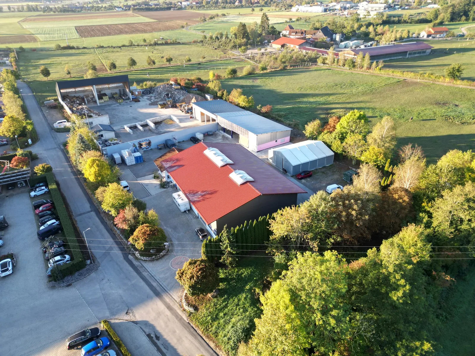
Metzger-Eibisch GmbH. From Upper Swabia, operating internationally.
Metzger-Eibisch GmbH from Upper Swabia combines experience in electrical engineering, metalwork and mechanical engineering. In our own installation business, the HP SitePrint is in frequent use internationally – and we now offer this experience as a service to other companies. Our standard: precise results, efficient processes and solutions our customers can rely on.
- REGION
- Lake Constance · Upper Swabia · Allgäu
- OPERATION
- Germany, Austria, Switzerland & international
- SERVICES
- Layout printing · 2D/3D surveying
FAQ
Frequently asked questions about layout printing.
Your question isn’t listed? Call us directly or send us a message.
We print floor plans, axes, pipe and cable routes, elevation marks or custom markings directly onto the floor – exactly according to your planning data. Content, colours and markings are tailored to each project.
Traditionally with a chalk line, or with a taut string line and a spray can. It works, but becomes much slower once the layout reaches a certain complexity. The printer transfers even complex geometries and labels directly from the CAD plan.
- The print is internally consistent – all dimensions fit together
- Significant time savings, especially for complex layouts
- On-site check: the result is verified for accuracy right away
- Clear guidance for every trade
Markings are executed with high precision in the millimetre range – directly from your digital plans, tracked by Leica total stations with 1″ angular accuracy.
A contact person on site, the CAD layout to be printed with reference points – fixed points or column axes – and the time frame. CAD or BIM data in DWG or DXF format is ideal. We prepare the data for printing.
Contact
Send us your plan.
We prepare your layout for printing, clarify the on-site conditions and send you an individual quote. Email is the fastest way to reach us.
CAD layout with reference points the layout to be printed – with fixed points or column axes as reference.
On-site contact someone who knows the area and how to access it.
Time frame when the area is clear and by when the layout must be in place.